No limitation Video PoE networks. Truth or fallacy?
PRESS RELEASE
23rd January 2019
No limitation Video PoE networks. Truth or fallacy?
Over the past few years, more and more manufacturers have been producing IP devices with higher power requirements. In the video sector, surveillance cameras with a combination of pan & tilt motors, heaters, windscreen wipers and IR illumination often require 60 or even up to 95 watts for their operation. However, this level of power consumption has not as yet been finally standardised.
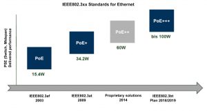
From its introduction in 2003, IEEE802.3af standard for PoE enables power of up to 15.4W to be transmitted over Cat.X cables. Not long after its introduction though it became clear that this standard was not sufficient. So in 2009, the new IEEE802.3at standard for PoE power up to 34.2 watts (PoE +) was adopted. To date, IP systems with these associated service classes 0, 3 and 4 can be incorporated and operated.
The Institute of Electrical and Electronics Engineers (IEEE) body for PoE has opposed the standardisation of the 60-Watt (PoE ++) solution, as this performance is considered proprietary and in any case not sufficient for future needs. As such, IEEE is currently working on the standard IEEE802.3bt, which should be adopted in early 2019. It is not yet clearly defined whether this standard will support 90 or 100 watts (although 120 watts is curently in demand), and whether it will be referenced as PoE +++, UPoE or HiPoE. In this context, it’s clear that there must also be an expansion of the performance classes. However, these are not yet completely ratified.
To cater for future developments and the IEEE802.3bt standard, barox already supplies ‘.bt ready’ switches, with PoE+++ models featuring upgraded port connectivity, and RAM firmware that can be overwritten to deal with the precise standard’s requirements.
Does 60 watts = 60 watts?
Due to the missing IEEE standard for 60 watts, this question unfortunately has to be answered in the negative. In the beginning, almost all manufacturers moved with the so-called two-chip principle to be the norm, i.e. 2 x 30-watt chipsets were installed on the PCBs of terminals for a 60-watt solution and combined, so that only one RJ45 external plug was required. Over time, pure 60-watt chipsets (the one-chip principle) were also developed in parallel, which ensured the compatibility of different PoE devices (e.g. camera and midspan) within one manufacturer. However, this leaves us with the legitimate question: do all 60-watt midspans work with all 60-watt cameras?
The answer is not so straight forward and needs to be considered to ensure device compatibility. On one hand, there’s no supporting IEEE standard and the possibility of manufacturing variants. On the other, there’s a lack of compatibility between the one-chip and two-chip principles. Since it’s (usually) not possible to tell from the outside of a device whether its PoE is based on a one or two-chip version, it’s advisable either to a) select PoE devices from a single manufacturer, to address the issue of compatibility, or b) to test the desired mix of preferred devices yourself prior to installation.
With a 60 watts standard nowhere in sight and solutions already available for demands of up to 120 watts, the required ‘Rat tail’ for operating these devices needs to be considered in greater detail, to cater for the demands placed by greater power loads. The current RJ45 plug requires improved alloys and modified technology to handle a manual plug disconnection, in order to protect the user and equipment against the arising sparks. Although the spark will always happen, since it is in the plug’s ‘war zone’ it will not affect the connection when the plug is back in place connected in the ‘peace zone’.
To prevent overheating and fire hazard, installers will need to give careful consideration to the type of transmission cable used. The cable cores need to be at least 1mm, so ordinary Cat5 cable will not suffice. Instead Cat5e, Cat6 or Cat7 cables should be specified to transport the greater power capacity, however this means heavier and more inflexible cables, and more costly installations.
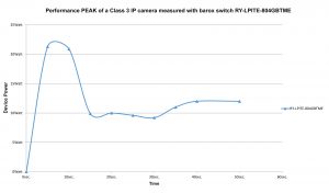
Representation of the ‘Switch-on’ performance curve of a typical IP/PoE camera
Video surveillance cameras are the most complicated IP terminal devices as they not only generate enormous power peaks during re-set, day/night switching, heater switch-on, and windshield wiper activation, but also produce higher data rates and need higher overall PoE for functions such as pan, tilt, zoom, illuminators and wiper, etc.
For an effective video surveillance system, the camera, video management and switch technology must integrate perfectly. Each of these components has its own specific task, and the switch analyses the network. This analysis includes measuring the data throughput rate, detecting potential data packet loss and checking cable quality. In addition, the switch can actively intervene when for example, a camera needs to be re-started.
Why use ‘Video-optimised’ switches
Due to its background activity, the switch is often given less attention, but this can lead to the following well-known problems: An IP camera powered by PoE fails for some inexplicable reason or hangs. The network connection is on, PoE is on, and the camera is fine, and yet there is no picture. Unplug the network, plug it in, and everything works. Another problem can be visible in the image display: pixelation, staircase formation, streaks or even a greenish tinge.
However, these issues can be avoided by using ‘Video-optimised’ switches, where video-optimised means that PoE camera performance is constantly monitored by the switch. In the event of camera failure, the switch automatically restarts the camera. If this fails, the switch issues an alarm message via SNMP, email or SMS. This is called active camera surveillance.
If all attached system cameras change their PoE rating from 0 to 4 due to increased PoE demand, or if the total budget is exceeded, either individual cameras or the entire switch will fail.
The video-optimised switch also has active PoE monitoring, so if for example, a defective camera starts to draw too much power from the switch, the switch will also create an alert, enabling maintenance to correct the cause (such as corroded plugs), to reduce the power consumption back to normal again. This feature protects the switch and its power supply.
In addition, PoE performance management should be considered. This feature allows for time-delayed booting of each PoE port, to prevent possible PoE power supply overload when logging on any attached cameras, or re-booting after a power failure.
Other useful features of a video switch include ‘Extra high’ backplane performance, where Extra high means that the switch has at least twice as much performance capacity compared to its Switchport services, i.e. with a 24-port full gigabit switch plus two gigabit uplinks, the backplane must be at least 52 Gigabit. This is the only way to ensure smooth video images can be transmitted with full port allocation.
In addition, jumbo frames up to 9,600 bytes must also be supported at 100 megabits per second, since these data packet sizes are only available in the video world at 100 megabits per second. If jumbo frames can only be processed at one gigabit per second, the probability of pixilation, podium formations and green cast in the image, or even a complete failure of the camera increases. For increased security and cyber security within the networks, features such as port security through MAC address restriction, IP detection and readability of certificates must also be included.
Conclusion
The demands on today’s video networks are growing. Not only in increasing power budgets but also the number of switches required per network. For effective and reliable camera networks, Video-optimised switches with built-in active monitoring features such as the Device Management Systems (DMS) that eliminate the need for separate network management services should be considered. Attention should also be given to using high-quality connectors and cable, such as Cat5e, to avoid excessive heat.
For more information on the barox range of professional video switches, customers can contact Clear Vision Technologies on 01580 212999, email info@cv-tech.co.uk, or visit www.cv-tech.co.uk
– Ends –
For further information, please contact:
Rudolf Rohr Chris Blake
Co-founder & Managing partner Technical Director
barox Kommunikation AG Clear Vision Technologies Ltd
Tel: +41 56 210 4520 Tel: +44 (0)1580 212999
Email: rohr.rudolf@barox.ch Email: sales@cv-tech.co.uk


